|
Technische Daten
|   |
|
Technische Daten
| |
|
Transportbedingungen: |
|||||||||||||||||||||||||||||||||||
|
Temperaturbereich: |
-10 bis 70° C |
||||||||||||||||||||||||||||||||||
|
Transport und Lagerung dürfen nur in trockenen Räumlichkeiten erfolgen |
|||||||||||||||||||||||||||||||||||
|
|
|||||||||||||||||||||||||||||||||||
|
Betriebsbedingungen: |
|||||||||||||||||||||||||||||||||||
|
Netzspannung: |
230 Volt |
||||||||||||||||||||||||||||||||||
|
Netzfrequenz: |
50 Hz |
||||||||||||||||||||||||||||||||||
|
Leistungsaufnahme Steuergerät: |
115 VA |
||||||||||||||||||||||||||||||||||
|
Temperaturbereich: |
+15º C bis +35º C (Temperaturen über 40º C während des Betriebes können das Gerät schädigen !) |
||||||||||||||||||||||||||||||||||
|
Relative Luftfeuchtigkeit: |
30% bis 93% |
||||||||||||||||||||||||||||||||||
|
Anwärmzeit : |
2 Minuten |
||||||||||||||||||||||||||||||||||
|
Höhe: |
≤ 2000m |
||||||||||||||||||||||||||||||||||
|
Magnetfelder : |
gemäß IEC 61000-4-8 (siehe nachstehend EMV-Spezifikation) |
||||||||||||||||||||||||||||||||||
|
Hochfrequenzfelder : |
gemäß IEC 61000-4-3 und IEC 61000-4-6 (siehe nachstehend EMV-Spezifikation) |
||||||||||||||||||||||||||||||||||
|
ACAM kann, wenn es starken Elektromagnetischen Feldern ausgesetzt wird zu Einschränkungen der Bedienung bis hin zum Ausfall führen.
Im Falle eines Absturzes ist ACAM so entwickelt und geprüft, dass keine Gesundheitsgefahr für den Anwender oder Patienten von ACAM ausgeht. Im Falle starker elektromagnetischer Störungen kann es vereinzelt zu hörbaren, jedoch nicht gesundheitsgefährdenden Schallereignissen aus angeschlossenen Schallwandlern kommen. Im Falle eines Absturzes des Steuerrechners oder der ACAM werden die Schallwandlerausgänge stumm geschaltet. Der Ausschaltvorgang kann als leises Knacken hörbar sein. |
|||||||||||||||||||||||||||||||||||
|
ACAM 5 ist gem�� der IEC 60601-1-2 (Anforderungen an die Elektromagnetische Vertr�glichkeit f�r Medizinische elektrische Ger�te) wie folgt spezifiziert:
|
|||||||||||||||||||||||||||||||||||
|
Abmessungen: |
|||||||||||||||||||||||||||||||||||
|
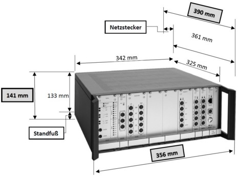
Grundgerät (Steuergerät): |
342 x 325 x 133 mm (B x T x H) |
||||||||||||||||||||||||||||||||||
|
Kleine, offene Meßbox: |
200 x 200 x 120 mm (B x T x H) |
||||||||||||||||||||||||||||||||||
|
Große, geschlossene Meßbox: |
400 x 330 x 300 mm (B x T x H) |
||||||||||||||||||||||||||||||||||
|
|
|||||||||||||||||||||||||||||||||||
|
Gewicht: |
|||||||||||||||||||||||||||||||||||
|
Grundgerät (Steuergerät): |
8 kg |
||||||||||||||||||||||||||||||||||
|
Kleine, offene Meßbox: |
2,5 kg |
||||||||||||||||||||||||||||||||||
|
Große, geschlossene Meßbox: |
12,5 kg |
||||||||||||||||||||||||||||||||||
|
Eingangsempfindlichkeiten: |
|||||||||||||||||||||||||||||||||||
|
Mikrofoneingang Meßbox: |
10 KOhm bei 1KHz |
||||||||||||||||||||||||||||||||||
|
Mikrofoneingang Insitu: |
1 KOhm bei 1KHz |
||||||||||||||||||||||||||||||||||
|
Mikrofonempfindichkeit (Meßbox und Insitu): |
10 mV/Pa +/- 2,5 dB |
||||||||||||||||||||||||||||||||||
|
Batteriemessung: |
> 1 MOhm |
||||||||||||||||||||||||||||||||||
|
Externe Eingänge 1 bis 4: |
10 kOhm bei 1kHz 620 mV (RMS) sprachsimulierendes Rauschen am Eingang der ACAM (vom Freiburger Sprachtest) entspricht 0dB in der Aussteuerungsanzeige der Sprachaudiometrie. |
||||||||||||||||||||||||||||||||||
|
Mikrofon Mit- und Gegensprechen: |
10 kOhm bei 1 kHz Das Mit- und Gegensprechmikrofon sollte in einem Abstand von 50cm zum Akustiker aufgestellt werden. |
||||||||||||||||||||||||||||||||||
|
Ausgangs Impedanzen: |
|||||||||||||||||||||||||||||||||||
|
Kopfhörer: |
6 Ohm |
||||||||||||||||||||||||||||||||||
|
Knochenhörer: |
4 Ohm |
||||||||||||||||||||||||||||||||||
|
Lautsprecher: |
4 Ohm |
||||||||||||||||||||||||||||||||||
|
Offener Kopfhörer (A2000): |
4 Ohm |
||||||||||||||||||||||||||||||||||
|
Einsteckhörer: |
10 Ohm |
||||||||||||||||||||||||||||||||||
|
Allgemeine Angaben: |
|||||||||||||||||||||||||||||||||||
|
Das Audiometer entspricht EN 60645–1:2018, EN 60645–2:1997; ANSI S3.6. Es sind Verfahren und Abläufe gemäß DIN ISO 8253 – 1:2011 , DIN ISO 8253 – 2:2010 und DIN ISO 8253 – 3:2012 anwendbar oder integriert. Die Skalierung entspricht der DIN ISO 16832:2007. Messungen an der Messbox entsprechen der DIN EN 60118-0:2020, DIN EN 60118-7:2006 und DIN EN 60118-15:2012 und ANSI S3.22 Die Insitu Messung entspricht DIN EN 61669:2018/ und ANSI S3.46. Verfahren, Bezeichnungen und Abläufe entsprechen der DIN ISO 12124:2002. Es werden die Richtlinein für Medizinprodukte RL 93/42/EEC Typ IIb erfüllt. Ein Qualitätssicherungsystem nach EN 13485 ist etabliert und wird überwacht. Identifikationsnummer: 0482. Es werden die Sicherheitsanforderungen der EN 60601-1 Klasse 1, Typ B, 60601-1-1 und 60601-1-2 sowie UL 2601-1 erfüllt. |
|||||||||||||||||||||||||||||||||||
|
Audiometerklasse: |
Klasse 2 Typ AE (Pegel Klasse 1) nach EN 60645-1,EN 60645-2 ANSI S3.6 |
||||||||||||||||||||||||||||||||||
|
Wartung und Kalibrierung: |
Gemäß EN 8253-1 Stufe A: Nach 80 Starts, oder nach 30 Tagen
|
||||||||||||||||||||||||||||||||||
|
Kopfhörer: |
Radioear DD45, DD450 Erforderliche Andrückkraft: 4,5 N ± 0,5 N |
||||||||||||||||||||||||||||||||||
|
Knochenhörer: |
Radioear Typ B 71 Erforderliche Andrückkraft: 5,4 N ± 0,5 N |
||||||||||||||||||||||||||||||||||
|
Lautsprecher: |
acousticon Typ db105 oder db99 |
||||||||||||||||||||||||||||||||||
|
Einsteckhörer: |
Etymotic Research Typ ER 3 A |
||||||||||||||||||||||||||||||||||
|
Offener Kopfhörer |
acousticon A 1000 acousticon A 2000 |
||||||||||||||||||||||||||||||||||
|
Langzeitstabilität nach (60645-1) |
<0,2 dB |
||||||||||||||||||||||||||||||||||
|
Temperaturabweichungen (nach 60645-1) |
zwischen 15° und 35° < 1dB |
||||||||||||||||||||||||||||||||||
|
Meßbox: |
|||||||||||||||||||||||||||||||||||
|
Eingangspegelbereich: |
20 dB - 100 dB (Ref. 20 µPa) |
||||||||||||||||||||||||||||||||||
|
Eingangspegelgenauigkeit: |
besser 1,5dB bis 2000 Hz besser 2,5dB von 2kHz - 5kHz |
||||||||||||||||||||||||||||||||||
|
Frequenzbereich: |
100 Hz - 10000 Hz |
||||||||||||||||||||||||||||||||||
|
Messbereich: |
<30 dB - >140 dB (Ref. 20 µPa) |
||||||||||||||||||||||||||||||||||
|
Messgenauigkeit: |
1dB bis 2000 Hz ; 1,5dB von 2kHz - 5kHz |
||||||||||||||||||||||||||||||||||
|
Induktion: |
Feldstärke < 0.1 mA/m bis >1 A/m |
||||||||||||||||||||||||||||||||||
|
Betriebsstrom: |
0.01mA bis 20mA +/- 0.01mA |
||||||||||||||||||||||||||||||||||
|
Betriebsspannung: |
0.6 Volt bis 3 Volt in Schritten zu 0.01 Volt. Genauigkeit 0.01Volt |
||||||||||||||||||||||||||||||||||
|
Batteriemessung: |
Messbereich 0 Volt bis 1.5 Volt, Genauigkeit 0.01 Volt
|
||||||||||||||||||||||||||||||||||
|
Kuppler: |
2ccm nach IEC 60318-5
0,4ccm nach IEC 60318-8 |
||||||||||||||||||||||||||||||||||
|
Kalibrierung: |
Siehe Kapitel: Kalibrieren |
||||||||||||||||||||||||||||||||||
|
Messignale: |
Sinuston mit 226 Frequenzen (inklusive der Frequenzen nach ISO 266),Rauscharten: Terzen, Weißes, Rosa, Sprachsimulierend, ICRA;Burst, CHIRP, Sprache, ISTS, natürliche Geräusche, Externe Zufuhr |
||||||||||||||||||||||||||||||||||
|
Auswertungen: |
RMS (Zeitbewertung 1ms bis >1 Min), FFT, Perzentilanalyse (nach IEC 118-15), Gruppenlaufzeit, Statisches und Dynamischen CV, Wasserfalldiagramm, Sonogramm, Spektren, Pegelverläufe, Pegelhäufigkeit, Enveloppenspektrum, Rauhigkeit, Schärfe, Lautheit, Nachhallzeit |
||||||||||||||||||||||||||||||||||
|
Eingangspegelbereich: |
30 dB - 100 dB (Ref. 20 µPa) |
||||||||||||||||||||||||||||||||||
|
Eingangspegelgenauigkeit: |
besser 1,5dB bis 2000 Hz besser 2,5dB von 2kHz - 5kHz* |
||||||||||||||||||||||||||||||||||
|
Frequenzbereich: |
100 Hz - 10000 Hz |
||||||||||||||||||||||||||||||||||
|
Messbereich |
<30 dB - >140 dB (Ref. 20 µPa) |
||||||||||||||||||||||||||||||||||
|
Messgenauigkeit |
1dB bis 2000 Hz*; 1,5dB von 2kHz - 5kHz* |
||||||||||||||||||||||||||||||||||
|
Entzerrung |
Über Variable FIR FIlter |
||||||||||||||||||||||||||||||||||
|
Kalibrierung |
Siehe Kapitel: Kalibrieren |
||||||||||||||||||||||||||||||||||
|
Messignale: |
Sinuston mit 226 Frequenzen (inklusive der Frequenzen nach ISO 266), Weißes Rauschen, ICRA Rauschen, CHIRP, Sprache, ISTS, natürliche Geräusche, Externe Zufuhr. |
||||||||||||||||||||||||||||||||||
|
Auswertungen: |
RMS, FFT, Perzentilanalyse (nach IEC 118-15) |
||||||||||||||||||||||||||||||||||
|
*Diese Werte sind abhängig von den Umgebungsbedíngungen. Die oben angegebenen Werte wurden unter „idealisierten“ Bedingungen ermittelt. |
|||||||||||||||||||||||||||||||||||
|
Tonaudiometer: |
|||||||||||||||||||||||||||||||||||
|
Kalibrierungen: |
|||||||||||||||||||||||||||||||||||
|
Luftleitung: |
EN 389-1 am Kuppler nach EN 60318-1 oder EN 60318-3 |
||||||||||||||||||||||||||||||||||
|
Knochenleitung: |
EN 389-3 am Kuppler nach EN 60318-6 Kalibrierung gilt für den Aufsatz auf den Mastoid |
||||||||||||||||||||||||||||||||||
|
Lautsprecher: |
EN 389-7 mit Schallpegelmesser Klasse 1 in 1m Abstand |
||||||||||||||||||||||||||||||||||
|
Einsteckhörer: |
EN 389-2 am Kuppler nach 60318-5 |
||||||||||||||||||||||||||||||||||
|
Verdeckungsageräusch: |
EN 389-4 Am Kuppler nach nach EN 60318-1 oder EN 60318-3 und Schallpegelmesser der Klasse 1 |
||||||||||||||||||||||||||||||||||
|
Spezifikationen: |
|||||||||||||||||||||||||||||||||||
|
Verdeckungsgeräusch*1 |
Schmalbandrauschen 1/3 Oktave mit > 24 dB/Okt |
||||||||||||||||||||||||||||||||||
|
Art der Modulation des Sinustons |
Frequenzmodulation (FM) |
||||||||||||||||||||||||||||||||||
|
Art der Modulation (FM) |
Sinusförmig (Verzerrung <1%) |
||||||||||||||||||||||||||||||||||
|
Modulationsfrequenz (FM) |
1.1 Hz bis 66 Hz +/- 10 % |
||||||||||||||||||||||||||||||||||
|
Modulationshub (FM) |
0.1 % bis 100 % +/- 1% |
||||||||||||||||||||||||||||||||||
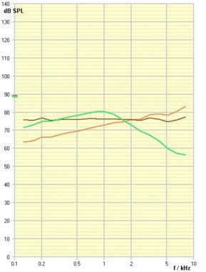
|
Abb.: Terzbandanalyse der Rauscharten bei einem Pegel von 90dB (SPL) |
*1 Neben dem Schmalbandrauschen als Standardverdeckungsgeräusch kann auch Sprachsimulierendes Rauschen, weißes Rauschen oder rosa Rauschen eingestellt werden. Bitte beachten Sie , dass die Verdeckungseigenschaften dieser Rauscharten bei der Tonaudiometrie zu Fehlerhaften Ergebnissen führen können da die Verdeckung im Vergleich zum Schmalbandrauschen meist geringer ist. Die verschiedenen Rauscharten haben verschiedene Spektren (hier Terzbandanalyse):
Meist werden diese Rauscharten verwendet um Mithörschwellen zu messen (z.b.: Langebecksche Geräuschaudiometrie). Für die Vertäubung in der Tonaudiometrie sind sie nicht geeignet. In besonderen Einzelfällen (z.B. wenn Tinnitus vorliegt) kann die Verwendung dieser Rauscharten jedoch angebracht sein. Um eine Vertäubung des Gegenohres zu erziehlen sollte dann der Pegel um wenigstens 15dB höher eingestellt werden als es bei Schmalbandrauschen üblich ist. |
||||||||||||||||||||||||||||||||||
|
Siehe auch: Audiometer: Kalibrier-, Korrektur- und Maximalwerte |
|||||||||||||||||||||||||||||||||||
|
Sprachaudiometer: |
|||||||||||||||||||||||||||||||||||
|
Allgemeine Angaben: |
|||||||||||||||||||||||||||||||||||
|
Kopfhörer, Knochenhörer, Einsteckhörer, Lautsprecher und Offener Kopfhörer sind Freifeldendzerrt. Alle Pegelangaben sind Freifeldbezogen nach EN 60645-2 |
|||||||||||||||||||||||||||||||||||
|
Vertäubungsgeräusch |
nach EN 60645-2 |
||||||||||||||||||||||||||||||||||
|
Zulässiges Sprachtestmaterial |
nach EN 8253-3 |
||||||||||||||||||||||||||||||||||
|
Maximalpegel: |
|||||||||||||||||||||||||||||||||||
|
Kopfhörer: |
130dB Verzerrung: 0.81% bei 120dB 0,89% |
||||||||||||||||||||||||||||||||||
|
Freifeld: |
100dB Verzerrung: 14,9% bei 90dB 6,0% |
||||||||||||||||||||||||||||||||||
|
Knochenhörer: |
80 dB Verzerrung 11,2% bei 70dB 3,0% |
||||||||||||||||||||||||||||||||||
|
Einsteckhörer: |
130dB Verzerrung 2,35% bei 120dB 0,6% |
||||||||||||||||||||||||||||||||||
|
Offener Hörer: |
100 dB Verzerrung 1,67% bei 90dB 0,95% |
||||||||||||||||||||||||||||||||||
|
Kalibrierung: |
|||||||||||||||||||||||||||||||||||
|
Pegeleinstellung für Sprachsignal: |
in dB SPL (Ref. 20 µPa) |
||||||||||||||||||||||||||||||||||
|
Pegeleinstellung für Rauschsignal: |
in dB SPL (Ref. 20 µPa) |
||||||||||||||||||||||||||||||||||
|
Verwenden Sie nur Sprachtestmaterial, bei dem ein Kalibrierrauschen vorhanden ist, denn nur dieses Material gewährleistet eine korrekte Pegelwiedergabe und die in den Normen genannte Vergleichbarkeit. Siehe auch: CD Wiedergabe - Kalibrieren |
|||||||||||||||||||||||||||||||||||
|
Siehe auch: Audiometer: Kalibrier-, Korrektur- und Maximalwerte |
|||||||||||||||||||||||||||||||||||
|
|
|||||||||||||||||||||||||||||||||||
|
Hörfeldskalierung: |
|||||||||||||||||||||||||||||||||||
|
Pegelbereich |
0-100 dB über offenen Kopfhörer 0-90 dB über Lautsprecher 40-140 dB über Einsteckhörer |
||||||||||||||||||||||||||||||||||
|
Kalibrierung |
in dB SPL (Ref. 20 µPa) |
||||||||||||||||||||||||||||||||||
|
Freifeldentzerrung |
Ja |
||||||||||||||||||||||||||||||||||
|
Pegelabstufungen |
1dB (gamäß EN 60645-1) |
||||||||||||||||||||||||||||||||||
|
Signale |
Terzrauschen (1/3 Oktave) >48 dB / Oktave Flankensteilheit |
||||||||||||||||||||||||||||||||||
|
Antworteingabe |
Manuell über Maus oder über Eingabetableau |
||||||||||||||||||||||||||||||||||
|
Bezugskurve |
Gemäß Reihenuntersuchungen von Prof.Heller „Lorenz Funktion“ |
||||||||||||||||||||||||||||||||||
|
Fehleroptimierung |
Entfernungsquadratoptimierend |
||||||||||||||||||||||||||||||||||
|
Bildung der individuellen Funktion |
Lorenz Funktion |
||||||||||||||||||||||||||||||||||
Anschuß und Steckerbelegungen:
Die folgende Abbildung zeigt die Frontansicht des Steuergerätes. Je nach der von Ihnen gewünschten Ausstattung können sich mehr oder weniger Einschübe in Ihrem Gerät befinden.
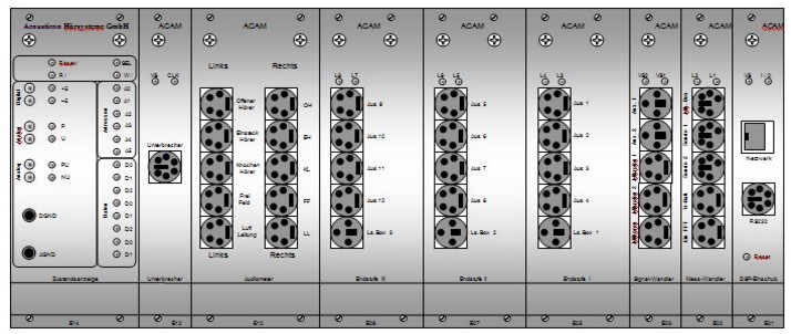
Falls Ihr ACAM-System mit einer Tischblende ausgestattet ist, befinden sich die Anschlüsse des Audiometers auf diesem Modul:
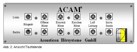
Neue Version (ab Mai 2010):
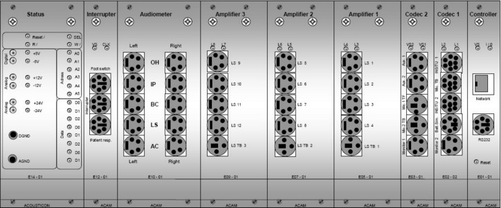
Frontansicht ACAM Steuergerät v 0.3
Belegungen der Buchsen:
|
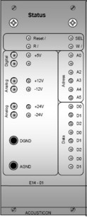
Einschub Status: |
|
||||||||||||||||||||||||
|
|
Normalerweise sind hier keine Stecker einzustecken. Der Einschub dient der Überwachung der Versorgungsspannungen und der Kontrolle des internen Bus. Auf der linken Seite des Einschubs befinden sich Buchsen um die Versorgungsspannungen zu messen. Diese werden nur für den Service benötigt. |
||||||||||||||||||||||||
|
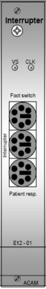
Interrupter: |
|
||||||||||||||||||||||||
|
|
Der Interrupter Einschub ist Bestandteil des Audiometers.
|
||||||||||||||||||||||||
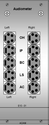
|
Audiometer: |
|
||||||||||||||||||||||||
|
|
Der Audiometereinschub ist Bestandteil des Audiometers.
|
||||||||||||||||||||||||
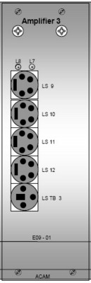
|
Amplifier 3 |
|
||||||||||||||||||||||||
|
|
Endstufe Nummer 3 zur Verwendung mehrerer Lautsprecher. Damit die Symbole in der Software übereinstimmen empfehlen wir die Lautsprecher entsprechend der folgenden Tabelle anzuschließen (aus dem Blickwinkel des Probanden).
|
||||||||||||||||||||||||
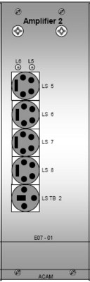
|
Amplifier 2 |
|
||||||||||||||||||||||||
|
|
Endstufe Nummer 2 zur Verwendung mehrerer Lautsprecher. Damit die Symbole in der Software übereinstimmen empfehlen wir die Lautsprecher entsprechend der folgenden Tabelle anzuschließen (aus dem Blickwinkel des Probanden).
|
||||||||||||||||||||||||
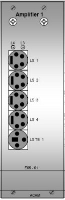
|
Amplifier 1 |
|
||||||||||||||||||||||||
|
|
Endstufe Nummer 1 zur Verwendung mehrerer Lautsprecher. Diese Endstufe wird immer benötigt. Damit die Symbole in der Software übereinstimmen empfehlen wir die Lautsprecher entsprechend der folgenden Tabelle anzuschließen (aus dem Blickwinkel des Probanden).
|
||||||||||||||||||||||||
|
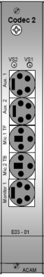
Codec 2 |
|
||||||||||||||||||||||||
|
|
Dieser Einschub beinhaltet den Codec ( Intelligenter AD und DA Wandler) Nummer 2 und die erforderliche Eingangselektronik.
|
||||||||||||||||||||||||
|
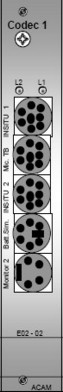
Codec 1 |
|
||||||||||||||||||||||||
|
|
Dieser Einschub beinhaltet den Codec ( Intelligenter AD und DA Wandler) Nummer 1 und die erforderliche Eingangselektronik.
|
||||||||||||||||||||||||
|
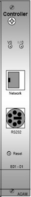
Controller |
|
||||||||||||||||||||||||
|
|
Dieser Einschub beinhaltet die Prozessoren.
|
||||||||||||||||||||||||