Checking the calibration:
It is necessary to perform regular calibrations to guarantee proper operation of the ACAM System. Calibration should be performed approximately once per week to once per month, depending on the frequency of use.
General Test Box Calibration:
- Separate the coupler from the coupler microphone.
- Place the coupler microphone and reference microphone in the circle designated for calibration in the test box. The microphones should be place at a distance of approximately 1 cm (Figure 36).
- Click <HIT> for test box, click <f> for frequency measurement and select calibrate in the context menu as seen in Figure 40.
- Click <go> to perform the calibration.
- The curve should show a flat line with a deviance of less than or equal to ± 2 dB (there is no true tolerance value) of the adjusted input sound pressure level. A calibration is necessary if the deviance exceeds ± 2 dB.
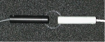
Figure 36: Reference microphone (left) and measuring microphone (right) in calibration position
Both microphone levels are displayed in the footer during a calibration measurement (Figure 37). The microphone levels should correspond to the adjusted input level. The level will be low if the microphones are defected.

Figure 37: Status bar during calibration measurement
A flat line should appear after successful calibration (Figure 38). The total level (small line on the left edge) should measure within the tolerance of ± 3 dB (there is no true tolerance value). If a flat line is not within the tolerance values after repeated calibration attempts, please contact ACOUSTICON live support.
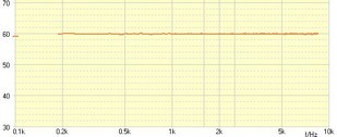
Figure 38: Calibration measurement without an instrument.
General Real Ear Measurement Calibration:
- Place the probe tube as close as possible to the reference microphone in front of the loudspeaker (Figure 39).
- Place the probe where the patient would be seated during a measurement. For example: place the probe on the backrest of the patient’s chair.
- Perform the calibration using a high input level (70 dB or higher): Click <REM> for real ear measurement, click <f> for frequency measurement and select calibrate in the context menu as seen in Figure 40.
- Click <go> to perform the calibration.
- A flat line response is evidence of a correct calibration. The total level should measure within the tolerance of an adjusted input level of ± 4 dB. The microphone is likely defective if there is no line following calibration. In this case, contact ACOUSTICON live support.
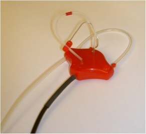
Figure 39: Real ear probe in calibration position
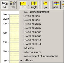
Figure 40: Selection for calibration
Step-by-Step Calibration Guide:
|
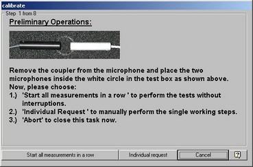
Figure 41: Step 1 of 8 - Example of the test box
|
Step 1 from 8 (Figure 41)
- Click <Start all measurements in a row> to perform each calibration step automatically, or:
- Click <Individual request>, to begin calibration in a specific section
- Click <cancel> to cancel the calibration.
Note:
The option <Start all measurements in a row> is best suited for daily use.
If two real ear probes are connected to the ACAM System, the calibration will need to be performed twice; once for each side (ear).
|
|
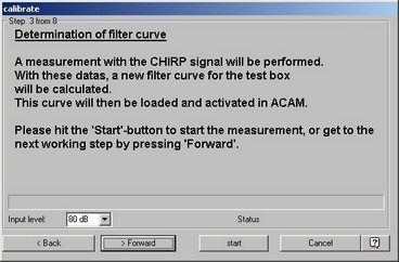
Figure 42: Measure individual filter curve.
|
Step 3 from 8 (Figure 42)
- The first measure is performed. This step is omitted in the real ear measurement calibration.
- An individual filter curve is measured which compensates non-linearities of the loudspeakers.
- Click <Forward> to continue for each of the steps.
|
|
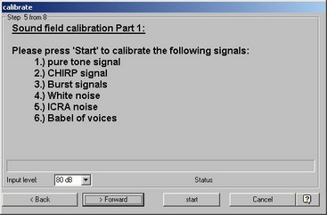
Figure 43: Soundfield calibration part 1.
|
Step 5 from 8 (Figure 43)
- A second measurement is performed.
- Various signals are presented to the loudspeaker and "regulated" until the adjusted level is met (80 dB in the example).
|
|
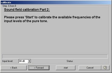
Figure 44: Soundfield calibration part 2.
|
Step 6 from 8 (Figure 44)
- A third measurement is performed. Note: this measurement is disabled in the setup of the real ear measurement; however, it can be enabled. When disabled, real ear measurements cannot be performed with pure tones and the corresponding menu items are disabled.
- Various signals are presented to the loudspeaker. The difference of the reference value (80 dB in the example) is measured and a new correction for the corresponding frequency is calculated.
|
|
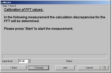
Figure 45: Calibration of the FFT values.
|
Step 7 from 8 (Figure 44)
- A fourth measurement is performed.
- Noise (for real ear) or CHIRP (for the test box) is presented to the loudspeaker. The difference values for the adjusted level and for each frequency are calculated (80 dB in the example).
Step 8 from 8
- Calibration is completed
- Click <finish> to close the window or the window will close automatically if <start all measurements in a row> was selected.
|
Possible calibration errors:
The following message (Figure 46) may appear when:
- Microphones is defective
- Sound card is defective
- Connection cables are disconnected (no signal).
If this message appears repeatedly, please contact ACOUSTICON live support.
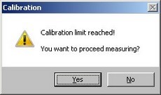
Figure 46: Calibration error message
Canceled Calibration:
The calibration may also cancel if the background noise is too loud or the measured level was below or above theacceptable limits. Canceling parameters can be changed in the setup menu.
Calibration Setup:
The calibration paramters can be adjusted in the setup menu of the Calibration tab.
Calibration results including quality of the microphone and loudspeaker are available to be viewed in the setup menu of the Calibration tab (Figure 47). .
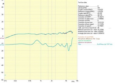
Figure 47: Calibration curves


![]()


